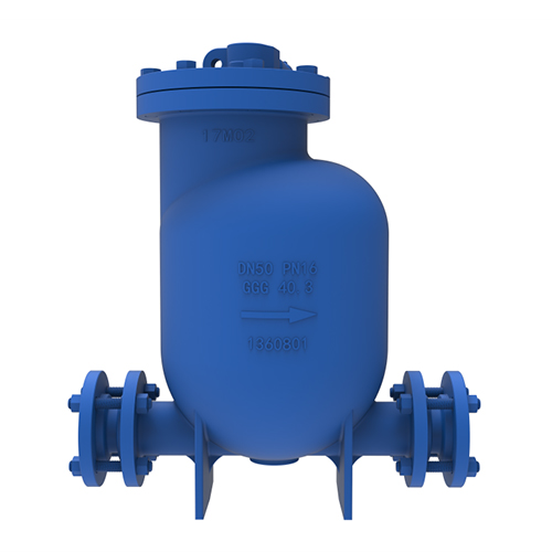
Relying on steam, compressed air and other gases as power, condensate is transported from a low-pressure area to a high-pressure area, or from a negative pressure area (vacuum) to a normal pressure area.
Removing and recycling condensate can improve production efficiency, save energy, reduce water treatment costs, and effectively utilize steam.
Firefighting water hammer phenomenon, prevent equipment damage, and improve reliability and safety.
Condensate water up to 198°C can be recovered without cavitation.
Automatic pumps have a series of advantages that are unmatched by other pumps, such as automatic control, no cavitation, simple maintenance, no need for electricity, water hammer resistance, large displacement, explosion-proof, and no noise. The pressure of the power steam (gas) determines the head. It is widely used in the transportation of condensate in steam systems and liquids with low viscosity and no volatility.
Get A Quote
Share:
Product Description
No electricity required (suitable for explosion-proof areas)
Strong and reliable
Float action mechanism
Large displacement
It uses steam or compressed air as power, and is easy to connect on site. It does not require power and is suitable for dangerous, dirty and humid environments.
The pump body is available in ductile iron, cast steel, and stainless steel, and the internal parts are made of stainless steel for corrosion resistance. Convenient replacement and maintenance. All internal parts are installed on the valve cover, and there is no need to remove the pipeline connection when replacing and maintaining.
No cavitation and mechanical seal problems inherent in electric pumps; reduces maintenance costs and downtime.
Automatic control, the water output is determined by the water inlet. The operating frequency increases when the condensate increases, decreases when it decreases, and stops working when there is no condensate. MET14 automatic pump provides flange or threaded connection, and the internal valve parts and float mechanism are all stainless steel. Stainless steel disc check valves are installed at the condensate inlet and outlet. The power medium (steam or gas) inlet and exhaust gas outlet are threaded. When used in combination with a float steam trap, condensate can be effectively removed from a temperature-controlled heat exchanger under any working conditions or even under vacuum.
MFP14 Working Principle
1. The fluid enters the pump body through the inlet check valve, causing the float to rise.
2. The residual gas/steam in the pump body is discharged from the opened exhaust/steam port, as shown in Figure 1. When the pump body is filled with water, the valve flip mechanism operates to open the power gas/steam inlet valve and close the gas/steam valve at the same time, as shown in Figure 2. This rapid flip action ensures the rapid conversion of the pump from the water intake stroke to the drainage stroke.
3. When the pressure inside the pump body exceeds the back pressure, the fluid pushes open the outlet check valve and enters the recovery system.
4. The liquid level in the pump body drops, and the float re-triggers the valve flip mechanism, closing the power gas/steam inlet and opening the exhaust gas/steam outlet.
5. The pressure inside the pump body drops, the fluid re-enters the pump body through the inlet check valve, and the cycle begins.
Power steam inlet/exhaust port DN15(1/2″)/DN25(1″)
BSP、NPT
Maximum motive gas inlet pressure
13.8bar
11bar
Maximum working pressure
13.8bar@198℃
11bar@188℃
Minimum operating temperature
0℃
Temperature limit (ambient)
-10°C~198℃
The total head or back pressure (static head plus the pressure in the recovery system) must be lower than the inlet pressure of the power fluid. The total head is calculated as follows: height H (meters) * 0.0981 + pressure in the recovery pipe (bar) + friction resistance of the fluid in the downstream pipe (bar).
When calculating the friction resistance of the fluid in the downstream pipeline, the fluid flow rate is taken as the smaller value of six times the actual cold water flow rate or 30,000 L/h.
Recommended water inlet height (based on the pump cover)
0.4m
Minimum water inlet height (based on pump cover)
0.2m (displacement reduced)
Standard pumping liquid specific gravity
1.8 to 1
Single cycle pump displacement
DN80x50
DNSO
19L
12.5L
Steam consumption
≤20kg/h
Air consumption
≤5.6m³/h
The displacement diagrams are based on a flooding height of 0.3m.
The head curve represents the net effective head (head + friction resistance).
In order to correctly select the drain pump, the following data is required:
·Power steam pressure when the pump is running (bar) ·Condensate load ·Vertical height of the condensate recovery pipe (m) ·Pressure in the condensate recovery pipe (ignore fluid flow friction resistance) ·Water inlet height of the pump
Note: It is recommended that the maximum power steam pressure and back pressure difference be 2-4 bar
Note: If you have any questions about the selection of the condensate recovery pump, or the working conditions are special, please provide the following information.
1. The nature of the pumped medium
2. The temperature of the pumped medium.
3. Flow rate of the pumped medium (Kg/h or L/h).
4. Initial lifting height, horizontal conveying distance and effective lifting height (effective lifting height = total lifting height – height of pipeline descent).
5. Power medium (base steam, compressed air or other gas).
6. Pressure of the power medium.
7. Condensate recovery pumps are usually used to pump condensate from open condensate tanks to recovery lines, but in certain specific cases they can be used to remove condensate from loss of flow conditions or even vacuum equipment.
Please clarify what the specific working conditions are.
How to select
Select a condensate recovery pump of appropriate diameter according to the power medium pressure, system back pressure, water inlet height and required displacement.
Condensate load 1500Kg/h
Power steam pressure when pump is running: 5.2 barg
Vertical lifting height of condensate recovery pipe: 9.2 m
Note: The recommended maximum power steam pressure and back pressure difference is 2-4barg
Selection Example First calculate the total effective head that the condensate recovery pump needs to overcome.
Total effective head = lifting height of condensate recovery pipe (9.2m) + pressure in condensate recovery pipe (1.7barg) The pressure in condensate recovery pipe is converted by the following formula:
P2=1.7barg-0.0981=17.3m pressure head (lift)
Therefore the total effective head is:
9.2m+17.3m=26.5m
According to the total effective head, the diameter of the condensate recovery pump can be determined by drawing on the displacement diagram on the next page: 1. Draw a horizontal line along 5.2barg on the vertical axis (power medium pressure); 2. Draw a curve for the 26.5m head: 3. Draw a straight line vertically downward from the intersection of the above two curves to intersect with the horizontal axis: 4. Obtain the displacement of the pump at the intersection (2400Kg/h).
Note: If the water inlet height is not 0.3m, the flow rate calculated above needs to be corrected by the corresponding water inlet height correction coefficient in the right table.
Pump diameter
% Back pressure/power medium pressure (BP/MP)
10%
20%
30%
40%
50%
60%
70%
80%
90%
Displacement correction factor
DN50
1.02
1.05
1.08
1.10
1.15
1.20
1.27
1.33
1.40
DN80×DN50
1.02
1.05
1.08
1.10
1.15
1.20
1.27
1.33
1.40
How to use the selection chart
Example: DN50 pump displacement
Displacement correction factor for flooding height
Water inlet height (m)
Displacement correction factor
DN50
DN80×DN50
0.15
0.75
0.80
0.30
1.00
1.00
0.60
1.20
1.05
0.90
1.30
1.15
Selection results In this example, the condensate recovery pump has a diameter of DN50.
The actual displacement of the pump after correction can reach:
0.75x2400Kg/h=1800Kg/h
Able to meet 1500Kg/h condensate water load
Note: If the motive medium is gas instead of steam, the corresponding correction factor must be found in the table below to correct the displacement of the condensate pump.