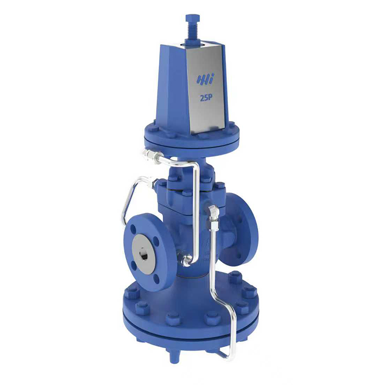
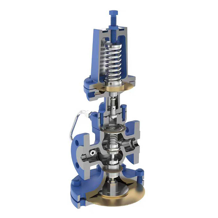
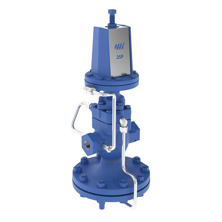
25P Self Acting Pilot Valve Type Pressure Reducing Valve
The 25P is a self-acting pilot-operated pressure reducing valve. It senses downstream pressure through an external pressure sensing tube, adjusts the main valve opening, and maintains stable pressure. The valve can be closed when there is no downstream load.
Get A Quote
Share:
Product Description
Constraints (Ductile)
● Design pressure (PMA): 21 bar ● Maximum operating pressure (PMO): 17.2 bar ● Maximum operating temperature (TMO): 232°C
Downstream Pressure Range
Three different colored springs are available to control downstream pressure: ● Yellow: 0.2 bar – 2.1 bar ● Blue: 1.4 bar – 7.0 bar ● Red: 5.6 bar – 14.0 bar
Bill of Materials
● Valve body and cover: QT400-18 ● Main valve seat and pilot valve seat: Martensitic stainless steel ● Main valve disc and pilot valve core: Martensitic stainless steel ● Pressure regulating spring: Silicon-chromium spring steel ● Other internal parts: Stainless steel
Flow
The table below shows the Cv value when the valve is fully open, which is used for safety valve selection.
Cv value
Caliber
1/2″
3/4″
1″
11/4″
1/2″
2″
21/2″
3″
4″
5″
Cv
3.48
6.5
10.5
14
20
35
56
74
115
123
Conversion formula: Cv(US) = Kv x 1.156
Dimensions/weight (approximately) mm and kg
model
25P
Nominal diameter
15
20
25
32
40
50
65
80
100
125
A(mm)
140
152
184
216
/
A1(mm)
160
166
205
216
240
288
316
361
400
B(mm)
193
219
269
346
397
C(mm)
309
322
338
297
294
325
D(mm)
157
171
179
208
354
367
410
E(mm)
466
479
501
546
651
661
735
Weight (Kg)
Thread
11
10.5
14
16.5
16
26
/
Flange
12
12.5
16
19
20.5
31.5
63
75
112
132
25P pressure reducing valve steam flow diagram
Note: This diagram is for reference only. For critical applications, it is recommended to select the appropriate flow meter based on CV (CV) calculations. The suggested CV value for actual operating conditions should be between 20% and 80% of the valve’s total CV. This flow meter is based on the installation of an external sensing tube. Without an external sensing tube, the flow rate will decrease. Under very low downstream pressure conditions, the flow rate reduction can reach up to 30%.
How to use flow charts The following two examples of saturated steam and superheated steam will explain how to use this flow chart.
Saturated steam Flow rate 5000 kg/h, pressure reduced from 8 bar to 5 bar. Finding the valve diameter that meets the flow requirements by moving vertically downwards from the fulcrum of the upstream pressure of 8 bar and the downstream pressure of 5 bar, an 80 mm valve is found to be the minimum acceptable diameter. Due to the higher specific volume of superheated steam, the data obtained from the diagram needs to be corrected. The correction factor for superheating at 55°C (100°F) is 0.95, and the correction factor for superheating at 110°C (200°F) is 0.9. Therefore, with an 80 mm valve, if the steam is superheated to 55°C, the flow rate is 5900 × 0.95 = 5600 kg/h, which is still sufficient to meet the required 5000 kg/h.